|
Price: USD2068
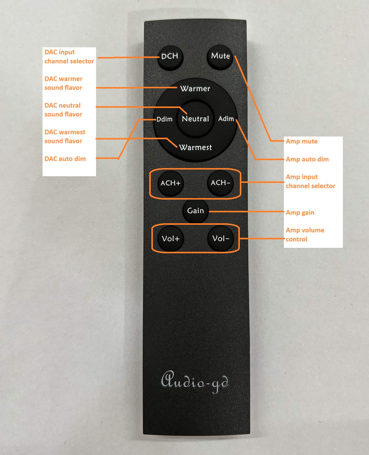
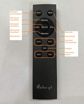
( Exclude shipping cost . Include combo remote controller that
can control the R8 MK3 and some lot audio-gd latest
preamp and headamp
models . It need two AAA batteries support by users .)
Organic glass top board
price : USD25

(Silver and black chassis versions available,
customer must inform while place the order ,otherwise we ship the
edition randomly:)
Please send your address, name
to audio-gd@vip.163.com
get the quote.
Please note:
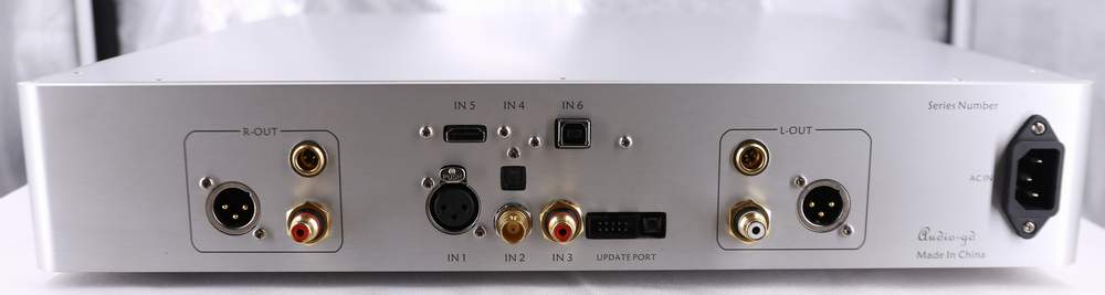
If user want the R8 MK3 work with the external clock input , can
update the firmware , the IN2 BNC input become the external 10MHz input. Download the R-8 EC firmware in the below link.The
Extermal clock must be 10MHz, 75 ohm, 1-3Vp-p level, recommend the
square wave output ,though sine wave also can work.
http://www.audio-gd.com/Firmwaredownload.htm
Customer also can ask we free update the R-8 EC firmware before
shipping.
Click to download the
driver of
Amanero
combo 384
Unique Jitter elimination technology:
Jitter has always been regarded as
the root cause for sound quality of digital systems to be inferior
to that of high-end analog systems.
In some traditional DAC designs, the clock
processing method is to follow and to restore the clock of the
signal source, and some designs also include the capacity of
reducing jitter, but with limitations when the jitter level is
large.
This common solution allows getting good
measurements in lab tests. But in actual use, most signal sources
have large jitter levels, so that the resulting sound quality will
not be satisfactory.
Some DACs worth only USD150 measure better
then than some well-selling DACs of foreign brands worth tens of
thousands. Who would think that this USD150 DAC is better? This
reminds me of when the China Insurance Research Institute tested a
direct collision between two brands of cars not long ago, and
netizens commented on the car that scored higher in the test: "It
has not failed the test, but it has not won the actual battle
either."
The following three product charts are from
three DACs of different brands, guess which one is the most
expensive? (The answer is at the bottom of this page)
Product A
Product B
 Product C
In
order to completely eliminate the influence of jitter in the
incoming signal, the R8 MK2 uses an asynchronous clocking process.
First it reads and stores
a considerable amount of signal source data to RAM, discard the
clock of the signal source, and directly use the high-performance
built-in Accusilicons to clock the output from the RAM. Since both
data and clock are handled by the FPGA, the impact of transmission
on jitter is neglectable. The jitter level is essentially the same
as what is specified for the TCXO clocks used by the R8 MK2.
The key to this processing method is to ensure the integrity of data
transmission, which is our technical secret. Realize that as soon as
a single data sample within a million is lost in the transmission, a
sharp and obvious cracking sound, like static, or a scratch on a
vinyl, will be heard during playback.
Mr. He is passionate about music and, too him, listening sessions
are a source of inspiration for new design ideas. Our cie does not
only have the advantage of having full control over software and
hardware technology, we also possess a correct understanding of
music reproduction. Without having to rely on outsourcing for R&D,
we can at any moment listen to the gears during development,
allowing the pursuit and realization of the most realistic sound
reproduction.
Because the local clock and the signal source clock are completely
isolated and run independently, the traditional jitter measurement
methods can not be applied, instead a special data acquisition
circuit is required to evaluate its level. For human beings, the
best test method is always through listening tests. A jitter-free
sound is very realistic and natural, as clear as pure water, and
very involving.
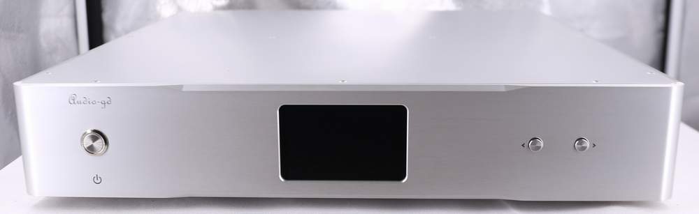
R-8 MK3 feature:
It has been 3
years since the R-8 was launched in 2018. Thanks to the fully
programmable circuits of the R-8, we have continuously updated the
firmware to improve the owner experience.
The R-8 MK3 was
designed and tested at the beginning of 2020, which was followed by
a year of continuous audition, software and hardware fine-tuning.
Using the latest discrete
servo stabilized power supply, whose performance is comparable to
batteries after more than a year of calibration and optimization for
each part of the circuit.
The DA parts use these new discrete servo stabilized power
supplies, the analog circuits are still powered by pure class-A
power supplies to achieve the best sound, as determined during
listening tests.
Productions and sales were not
scheduled until we were fully satisfied with how realistic the sound
was. The improvement is quite obvious compared to the previous
generation.
1.
Fully discrete parts are used in a truly balanced current
transmission design.
Four sets of fully discrete and
independent DSD hardware decoders.
Eight sets of fully discrete R-2R DA
modules to form a two-channel balanced push-pull decoder.
Using the latest
designed discrete servo stabilized power supply to feed the DA
circuits, the noise level is comparable to that of a battery, but
without the dry and thin sound characteristics of it, and thus the
product's operating temperature is significantly lower than that of
the previous model. The analog circuit are still powered by a pure
class-A regulated power supply for the best sound results (New upgrade)
2.
By listening to a
turntable and studying its sound for a long time, we have
successfully integrated the analog vinyl sound characteristics into
this product, this being allowed optionally through the front panel.
(New feature)
3.
Both the USB and HDMI
inputs are equipped with isolators, and two sets of linear power
supplies to separately supply power to the USB and HDMI modules
before the isolators to prevent interference from signal sources.
a, USB uses a two-way
transmission isolator, which not only transmits IIS signals to the
FPGA processor, but also receives the synchronous clock signal sent
by the FPGA processor.
The USB interface itself is no longer
equipped with clocks. The synchronous clock is applied to make the
signal transmission more accurate and upgrade sound quality to an
excellent level. The sound quality is now in fact better then with
the previous generation R-8 2020 version fed by the DI-20 (not quite as good as
with DI-20HE however).
b, the HDMI module is now equipped
with an independent isolator to improve the sound quality of the
HDMI input.
4. Display of the input signal
sampling rate function.
(New feature)
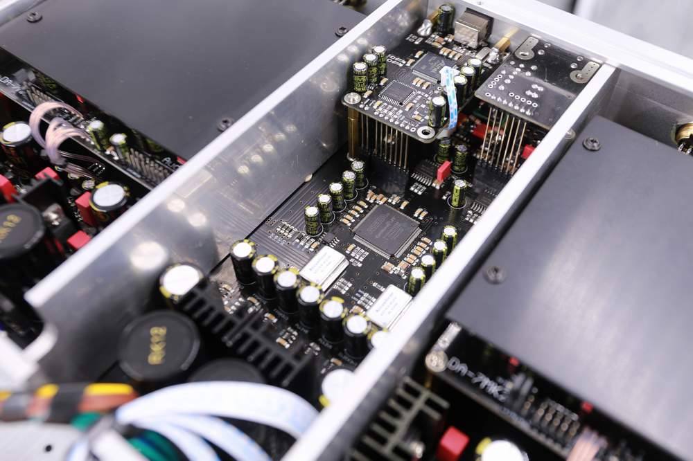
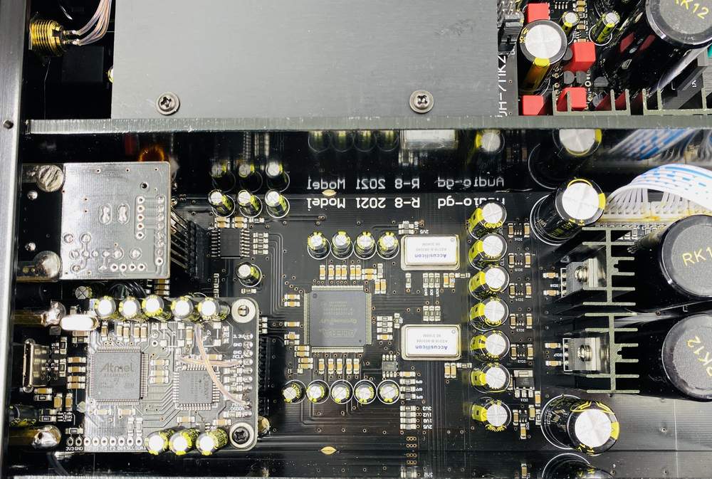
5. The
digital circuits of the whole DAC
are comprised of 1 FPGA and 5 CPLDs (both programmable devices),
which allow separating the different functional circuits and
preventing interference.
The FPGA operates using the
parallel data processing mode.
The IIS signal is serial data transmission. Each data bit requires
one clock cycle. One frame of left and right channel data requires
64 clock cycles, so stability over a 64 clock cycles is needed.
The parallel mode only needs one clock to transmit and process the
32-bit data of the left and right channels, which greatly improves
the processing speed and is less affected by the stability of the
clock.
IIS input data (USB and HDMI-IIS) is
reorganized into two sets of 32-bit parallel data as soon as it is
inputted. After the SPDIF signal is demodulated, it is
also sent to the next level of processing through two sets of 24-bit
parallel data.
DSD data is also reorganized into two groups of
64-bit parallel data processing as soon as it is inputted.
According to listening comparisons, the parallel processing mode can
make the sound clearer and more neutral, with better dynamics and a
more analog flavor.
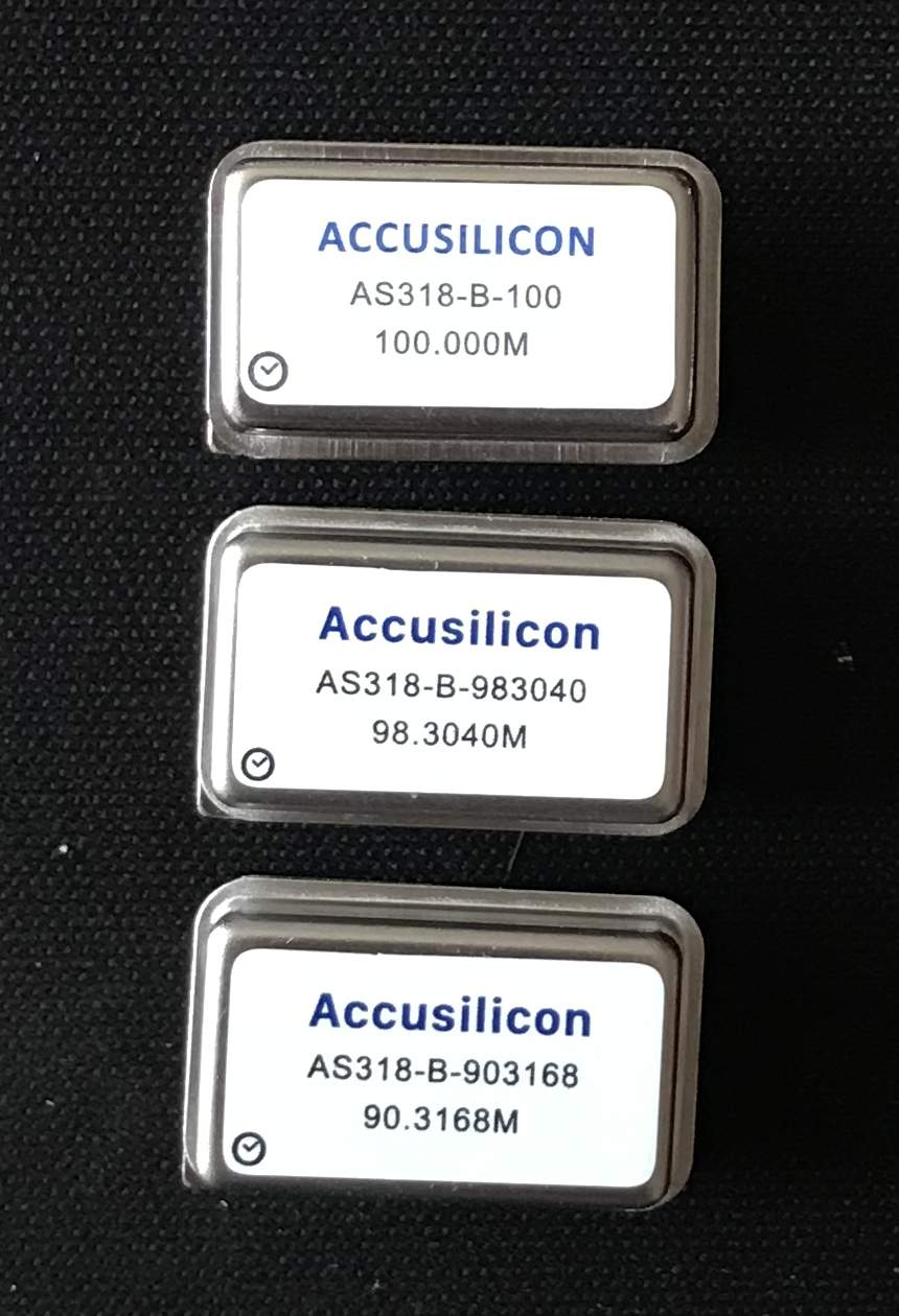
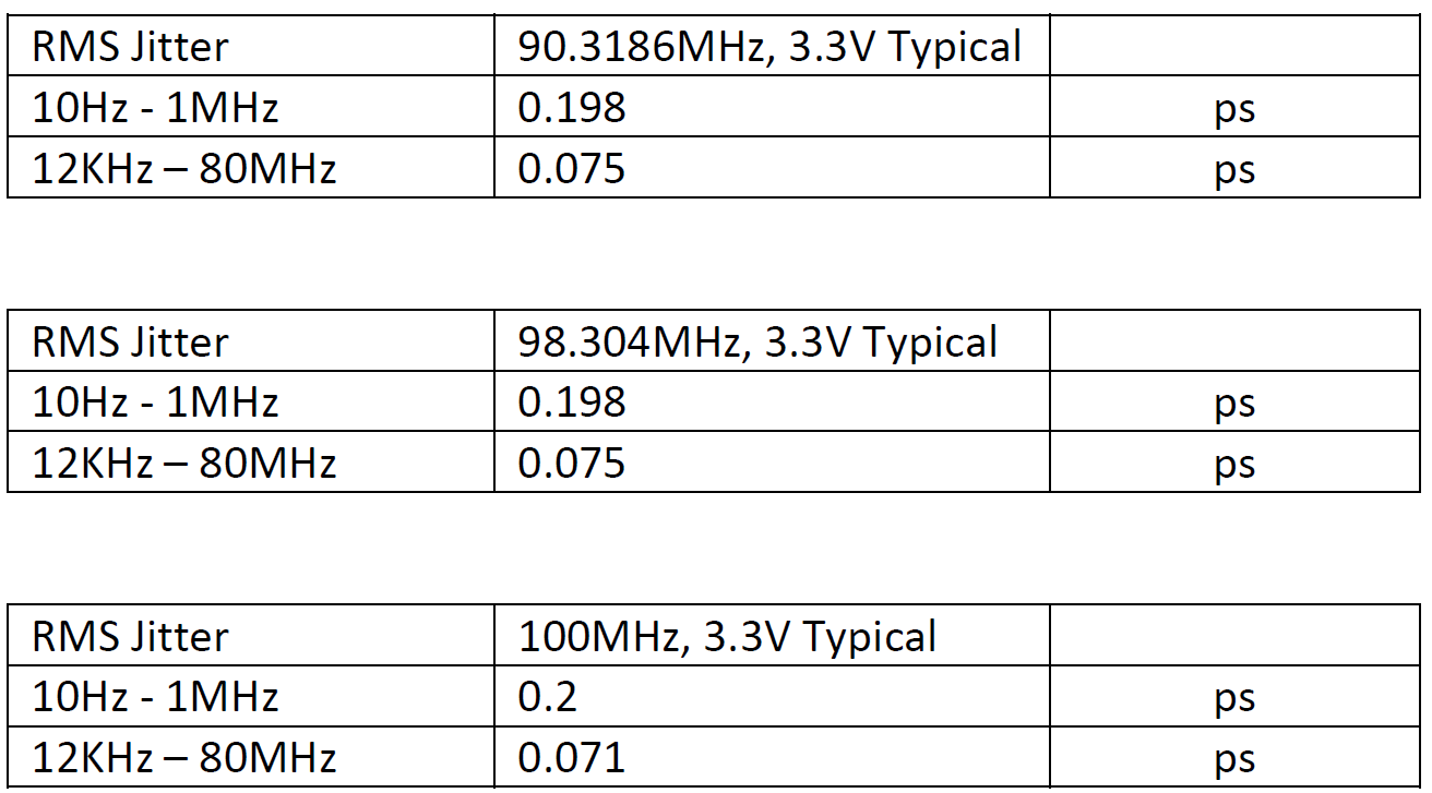
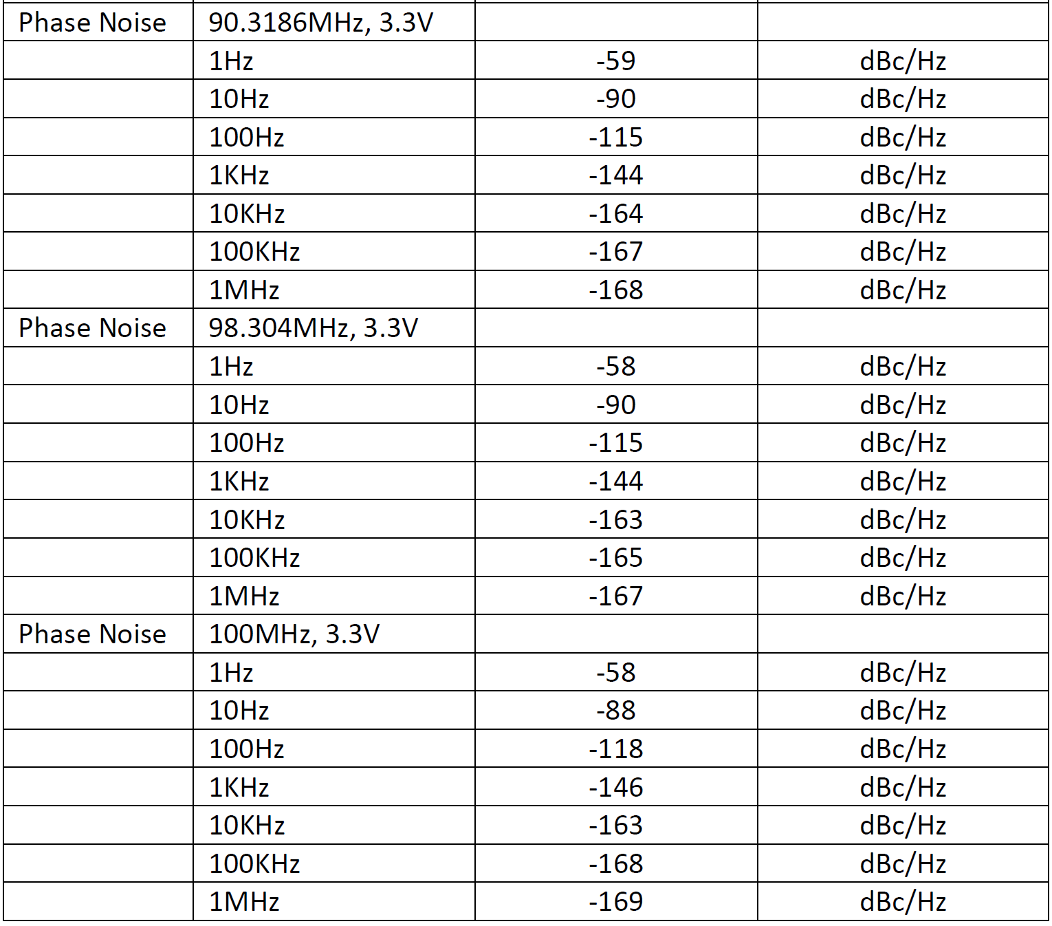
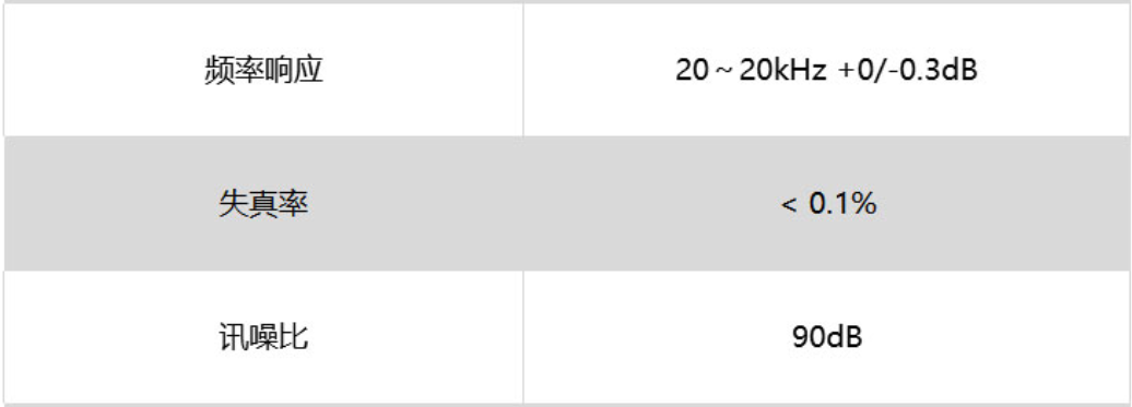
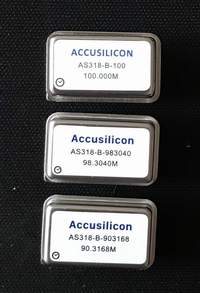
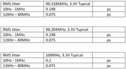
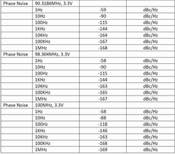
6. 2
top-notch Accusilicon TCXOs with
frequencies of 90 and 98MHz provide synchronization for the whole
unit, and they are applied to the playback of all data rates without
PLL up-conversion. The clock management design of the
new architecture makes the clock work more stably, which brings
higher transparency and more details.
7. DSD uses the built-in asynchronous
clock to enhance timing, which obviously improves the clarity and
dynamics of reproduction.
8. SPDIF supports DOP playback.
9. All digital mode settings can be changed on the front panel live.
10. A firmware upgrade port is
featured on the rear panel of the machine (no need to open to take
off the cover to upgrade the firmware).
The advantages and disadvantages
of R-2R DAC:
Advantages:
1, R-2R will not convert the
clock signal to the output signal.
2, R-2R is not sensitive to
jitter but Delta-Sigma is quite sensitive.
3, The output signal level of
R-2R is more accurate than Delta-Sigma.
Disadvantages:
1, R2R's harmonic distortion
can be quite low but not as low as the ES9038 PRO (Delta-Sigma)
harmonic distortion.
2, The accuracy and inherent
glitches of resistor ladders are not easy to deal with.
R-2R design popular in the market:
Whether it is DIY kits or
factory products, R-2R has become popular.
In the low-cost DIY kit market,
the usual design is based on the old MSB technology, but only retain
the signal conversion part and discard the exquisite design of the
original product.
This design uses data serial input to
a shift register IC to convert data to an analog signal. It is not
able to solve the technical problem of R-2R at all. The performance
of this design is completely dependent on the accuracy of the ladder
resistances.
The
factory products in the high-end market use quite complex technology
to solve the problems of R-2R, in order to achieve high performance
and sound quality. Some manufacturers use the serial control mode of
the shift register IC.
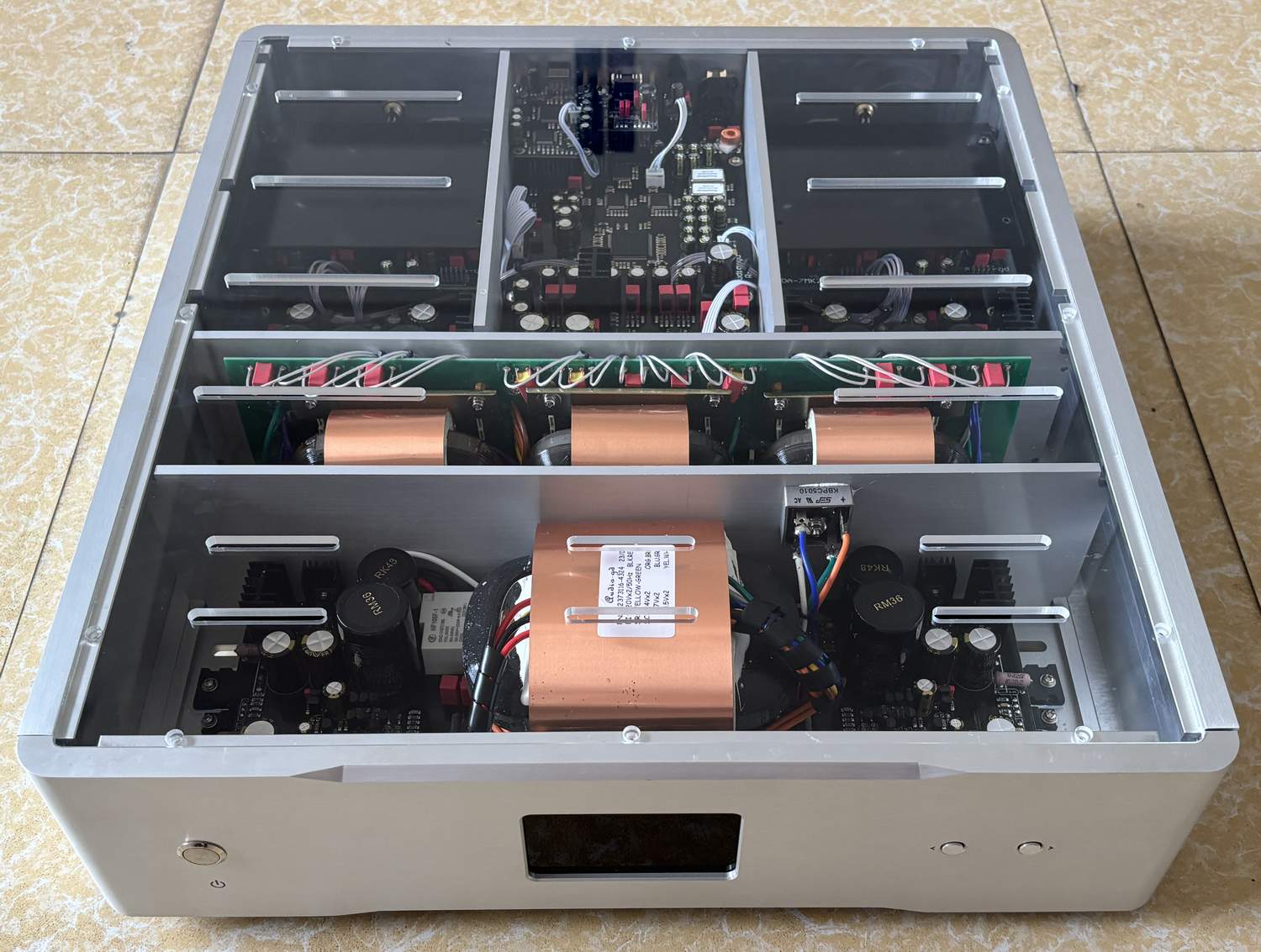
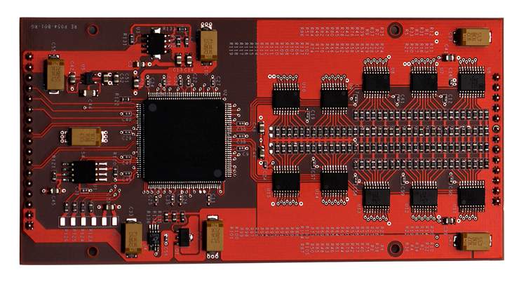
The design in the figure
below uses an FPGA to control the step resistance switching in
parallel. With the parallel control mode, the step resistance switch
of each bit is individually controlled, so it has ultra-high speed
(parallel mode only needs 1 clock cycle to output all bits, serial
mode requires at least 8 to 24 clock cycles) to send or update the
data, and can correct the data at any time to achieve an output
signal with low-distortion characteristics, and solve the problems
caused by resistance tolerances and switching glitches.
The accuracy of the step
resistance:
Many people only care
about the accuracy of the step resistances because they think that
R-2R depends essentially on the accuracy of the resistance.
Nowadays, 24 bit is a standard, but
can the precision of manufactured resistors reach 24 bit? Even with
only 16 bits, the accuracy requirement is 1/66536, and so 0.1%
(1/1000) of accuracy is completely inadequate. In fact, 0.01%
(1/10000) would still fail to meet the 16-bit requirement, let alone
24 bits.
Therefore, lowering accuracy of
the resistance is not enough to solve the problem. If there were
0.00001% resistors available on the market, it would meet the
requirement of 24 bits, but the inherent resistance of the switching
devices would completely wipe out this super high accuracy
advantage.
We need to solve the
problem technically, not just improve the accuracy of the
resistance. But we still use ultra-high precision resistors in our
products.
Ī@
Importunacy of the FPGA/CPLD:
On important thing to
underline about the FPGA/CPLDs is that they are programmable logic
array devices. Nowadays, FPGAs have been used in many high-end DAC
products, such as the popular ROCKNA WAVEDREAM DAC.
Since 2008, we have used
FPGA designs in DAC products. This machine is composed of one FPGA
and 5 CPLDs at the heart of digital processing.
The hardware layout
inside the FPGA can be designed and arranged through software,
therefore the hardware can be upgraded through software updates.
As a benefit, this
design has a high degree of flexibility. It allows improving sound
quality, adding functions, and keeping the product up-to-date, all
through software (firmware) updates.
Ī@
Responsibilities hor the FPGA/CPLDs:
1. the FPGA implements a
high-performance SPDIF demodulator (instead of using low-performance
SPDIF demodulator chips such as DIR9001, WM8805, AK411X, etc...).
2. Combining clocking and FIFO
technology to output data, it can be accurately synchronized to the
clock, and thus reject jitter.
3. Built-in 2X, 4X and 8X
digital filters and different NOS modes allow users to choose the
tone that best suits their personal taste.
4. Simulate the tonality of
vinyl disc playback through a unique design.
Fully
discrete output stage:
The last stage in the
signal journey is the analog output stage, and the output stage has
a decisive influence on the sound quality of the DAC.
No matter how excellent
digital circuit design is, without an excellent analog output stage
design, the sound quality will become extremely ordinary.
The analog output stage
is directly connected behind the DA 7 module, using only
through-hole components (not SMD).
The high-speed ACSS
amplifier is used for signal amplification and processing. The ACSS
amplifier is designed without negative feedback and works in the
current signal mode. It does not have to repeatedly transform the
signal between current and voltage like other designs.
The output buffer stage
is a single-ended pure class-A FET design, and the two groups are
connected in parallel to achieve a lower output impedance. All in
all, the output stage is working in a pure class-A state, with no
negative feedback at all, so that it can reproduce pure and lifelike
sound signals.
The DAC has four
built-in operational amplifiers to serve in the DC servo function,
so that the DAC can work without coupling capacitors, avoiding noise
and coloration. In the whole signal channels following the DA
module, no switching elements are used to achieve the truest and
purest sound quality.
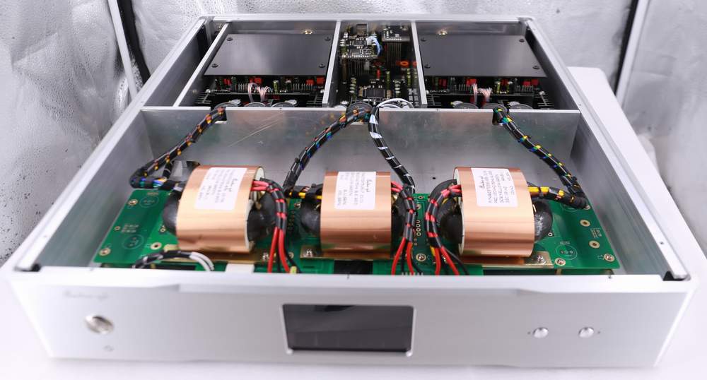
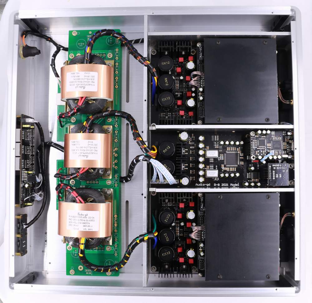
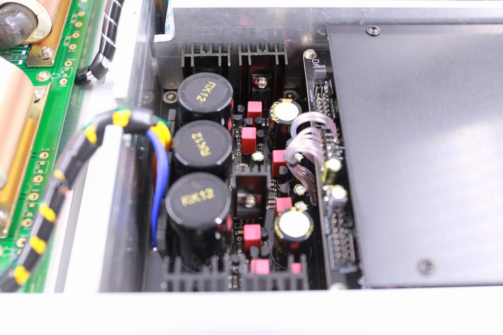
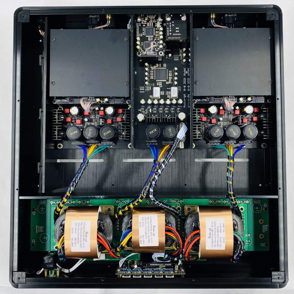
Powerful power supply design:
Use 3
high-performance R-core transformers with a total power of 135W and
more than 30,000 uF of audio-grade filtering capacitors to ensure
the purity of the power supply.
The digital parts DC power is distributed by 9 ultra high speed low
noise PSUs, they are group became the double stages
PSUs .
The analog parts DC power is distributed by
4 groups pure class A PSUs power supply to the analog output amps,
and 4 groups discrete serve PSUs that performance can rival to
battery power supply to the digital and
analog of the DA modules separately .
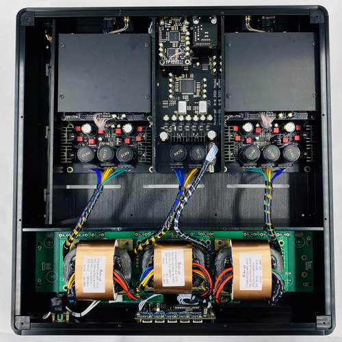
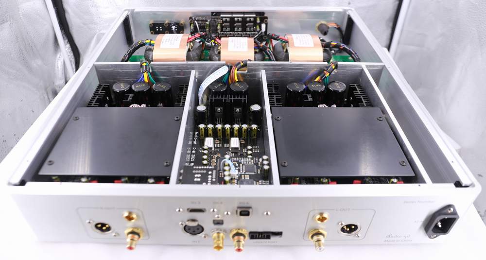
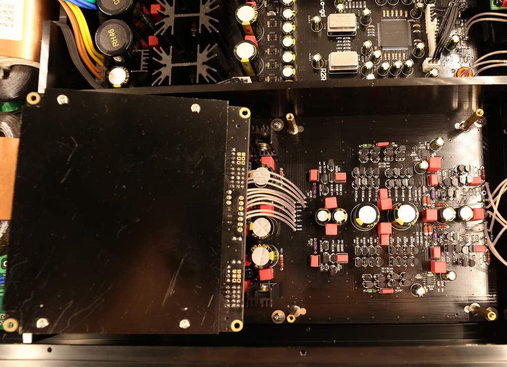
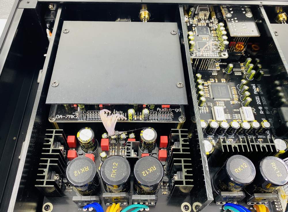
Layout :
The DAC uses 5mm thick
aluminum plates to separate the digital section, left and right
channel analog sections and transformer section to avoid mutual
interference between them.
The analog parts of
the left and right channels are symmetrically distributed on both
sides of the digital part, with the same signal path length and
distance, which makes the sound quality more even and accurate.
The DA 7 module is
installed between two aluminum plates to avoid interference from
other circuits. The complicated layout and installation procedure
have been chosen for the clearer and purer sound quality they bring,
and to make the sound field wider.

Product A ĪGUSD150 DAC
Product B ĪGUSD5000+ DAC American P brand DAC
Product C ĪG USD10000 British E
brand RIAA front
|