|
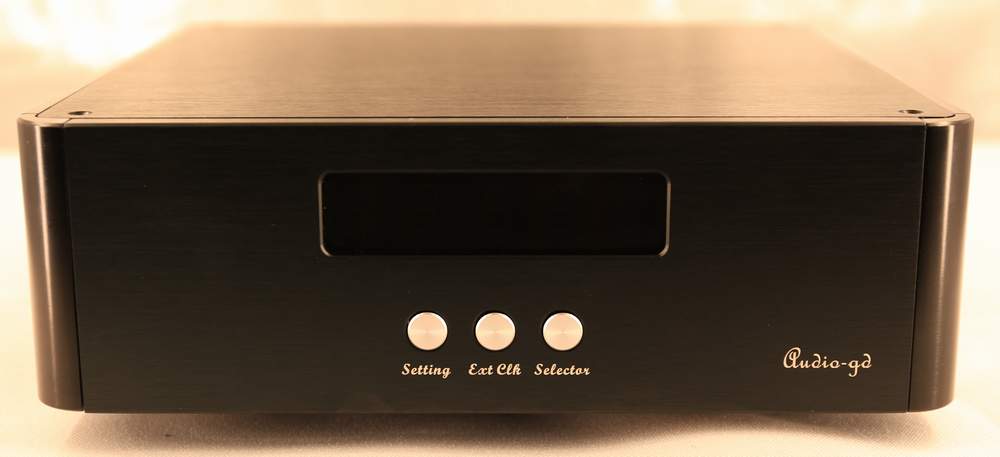
Faceplate
functions:
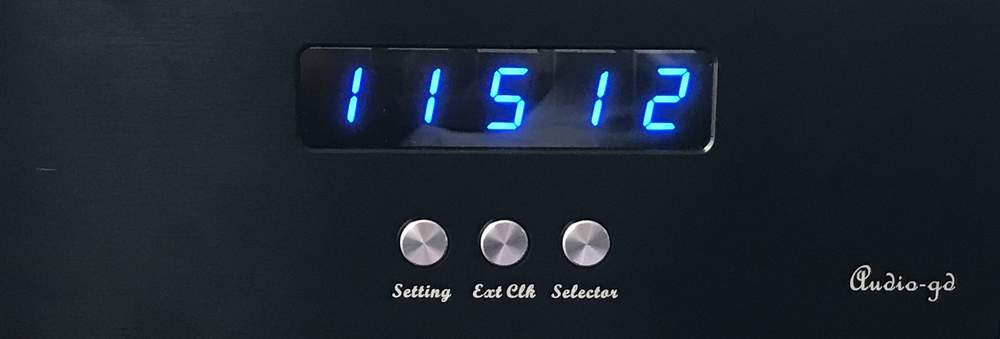
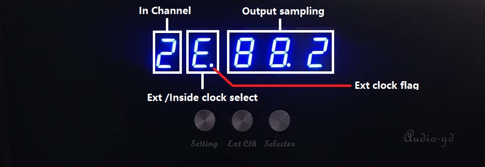
The leftmost display element:
The selected input, "1" indicates
the USB audio input is selected, "2" indicates the coaxial input .
The 2nd display element from the left:
External/internal clock, "I"
indicates the internal clock is selected, "E" indicates the external
clock .
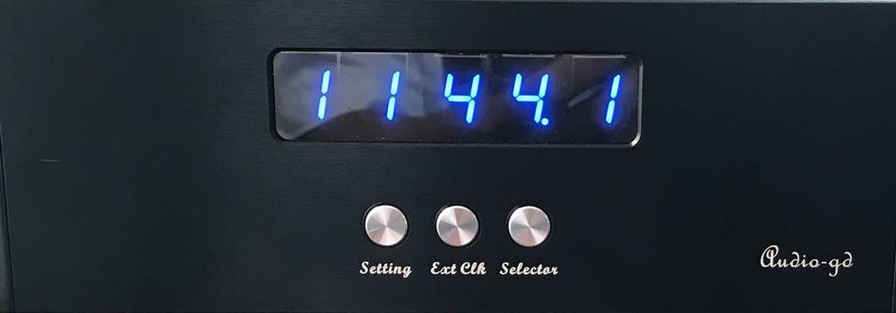
Remaining display elements :
Show the input/output
signal sampling rate. For example, with a PCM88.2K signal, the
display indicates "88.2" . >>>With a DSD512 signal, it indicates
"512" .
"Setting" button :
Push once to go into
the setting menu, the display will be flashing. Settings can then be
modified.
"Ext Clk" button :
Push to toggle
between the external and internal clock . While an external clock is
connected and powered on, you can select it. This is indicated by
the external clock flag being lit (see figure). Otherwise, the
external clock cannot be selected.
Please note : If the
external clock lose power, or the cable has bad connect , even
though select the external clock,the "E" will become "I" (Switch
back in inside clock) automatically for avoid output noise.
"Selector" button :
Selects the audio
input (coaxial or USB) .
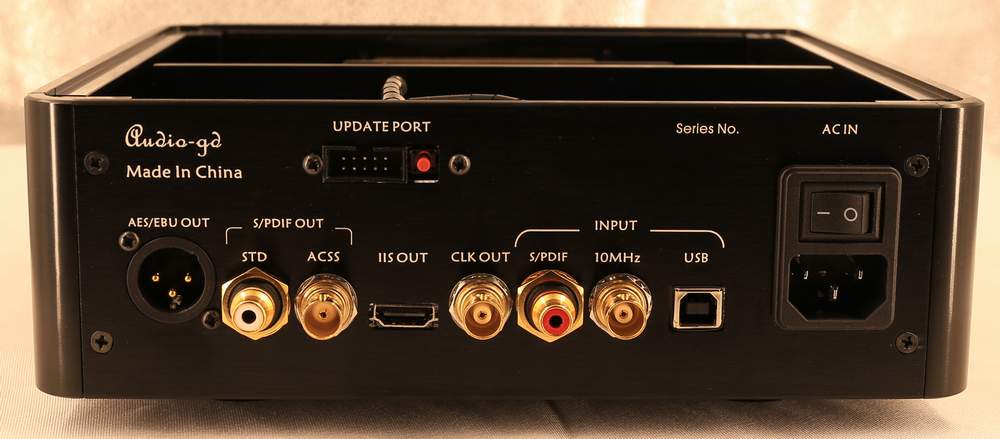
Rear plate
connectivity :
AES/EBU OUT :
AES/EBU output connector(5VPP @ 110
Ohm)。
S/PDIF OUT STD :
Standard coaxial output connector,
with built-in silver wire isolation transformer. (0.5VPP @ 75 Ohm).
S/PDIF OUT ACSS :
Output using current
transmission technology over coaxial (0.5VPP @ 75 Ohm).
This output applies the 2nd
generation coaxial ACSS technology, which offers even further
reduced signal degradation and better sound quality over a coaxial
cable .
In theory, when the DI
outputs the current coaxial signal to a DAC using a regular coaxial
input, thus receiving the current through a 75Ohms resistor, the
signal gets naturally converted to a 0.5VPP voltage coaxial signal.
Therefore, most DAC can receive this signal and will benefit from
this technology .
(Note that If the DAC's coaxial
input has a built-in transformer, or if the input impedance is not
75 ohm, or if the input sensitivity is not 0.5VPP @ 75Ohm, the ACSS
coaxial connection may not work properly ) .
IIS OUT :
IIS signal over HDMI
output (3.3V LVDS @ 110 Ohm). It only can work with DACs using the
exact same pin definition. It can NOT work with mainstream
audio/video devices featuring HDMI inputs, and connecting the DI to
such devices could damage it, in which case the warranty will not
cover the repairs.
CLK OUT :
Outputs 256fs main clock or
LRCK/WCLK
(3.3V LVDS @ 50 Ohm) . User-selectable .
INPUT S/PDIF :
RCA 75 Ohm coaxial audio input
(0.5VPP @ 75 Ohm) .
INPUT 10MHz :
External 10MHz clock
input (0.3VPP -3VPP @ 50 Ohm)
INPUT USB :
USB audio input(USB2.0/USB3.0)。
UPDATE PORT 10 pins port :
To connect the Altera Blaster and proceed
with an FPGA firmware update from Windows, using the Altera
programming software. These updates are meant for upgrading the
functionality and/or sound quality .
UPDATE PORT switch :
For updating the built-in Amanero
module's firmware through the USB input.
Amanero firmware download link:
https://www.amanero.com/combo384_firmware.htm
Amanero firmware update guide :
Please download the update tool and
guide from Amanero's official web . In the official update guide,
there is a step requiring that two pads be shorted more than 1
second on the Amanero module , while with the DI-Large, users only
need to push the red button for more than 1 second in order to
perform the same step . Other update steps are the exact same as in
the official guide.
Settings
function features:
"Setting" button :
Push once to access the
settings menu . The leftmost display element will flash , it means
the corresponding setting can be changed by pushing the "Selector"
button . While in the settings menu , push the "Setting" button once
more to access to next setting to the right, whose display element
will then blink.
"Ext Clk" button :
In the settings menu , push
this button to access the next setting to the left .
"Selector" button :
Push once to change the
flashing display element's corresponding setting .
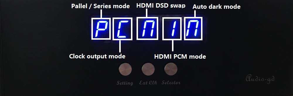
The 1st display element :
"P" (Parallel) means the signal will
be processed internally by the 32 bit (PCM) or 64 bit (DSD) parallel
mode . "S" (Serial) means the signal will be processed by the serial
mode.
The 2nd display element :
"C" (Clock) means the Clk OUT on the
backplate outputs a 256fs main clock , "L" (LRCK/WCLK) means the output is
the word clock .
The 3rd display element :
"n" (Non Swap) means the HDMI
outputs DSD with left and right channels following the Audio-gd
definition . "I" (Swap) means the DSD left and right channels
are inverted .
The 4th display element :
"1" means the PCM over HDMI i2s
output follows Audio-gd's definition . "2" mean the pins definition
follows other standard . (Read below for details ).
The 5th display element:
"A" (Auto) means the display will
automatically shut off after around 10 seconds if no buttons are
pushed. "n" (Non Auto ) means the display will remain on.
HDMI i2s output definition setting
:
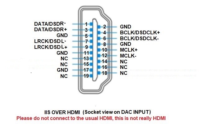
HDMI output mode 1:
The 3rd display element indicates "n"
(Non swap)
and the 4th indicates "1"
(In the setting menu) : i2s out follows the Audio-gd
i2s definition.

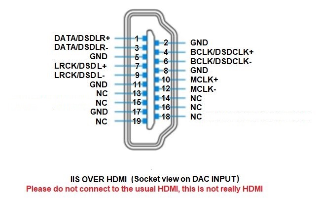
HDMI output mode 2:
The 3rd display element indicates "n"
(Non swap)
and the 4th indicates "2"
(In the setting menu) :
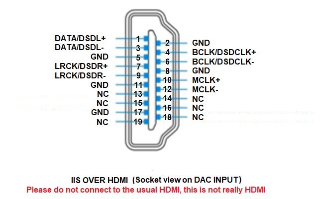
HDMI output mode 3:
The 3rd display element indicates "S" (Swap) and the 4th indicates "1"
(In the setting menu) :
HDMI output mode 4:
The 3rd display element indicates "S" (Swap) and the 4th indicates "2"
(In the setting menu) :
|