Wisdom in mind,   enthusiasm at heart.

Home Products Warranty Shop Contact Us Shipment Chinese

PSU-A
The most neutral sound reproduce PSU
Class A 3 Pins Discrete PSU
High Speed & Low Noise


Price:   USD16 (Exclude shipping cost)


       3 pins design, easy replace the 3 pins PSU-IC and normal PSU .
       Output Current 70mA or 140mA (Users select, default setting at 70mA) .
       Temperature Range : 0°C to 85°C
        Installation :L38 x W40 x H30   (mm, without feet)
        Quality Components: Custom order NOVER (England brand) , WIMA capacitor, DALE  Resistor.
        Extra thick gold plated PCB
 Applied: For CDP, DAC, Preamp and power amp gain stages modify . ( Can't working for laser and motors drive circuits in CDP)
 Note: This is a class A PSU, its current output had limit at 70/140 MA . If you want large power supply, please click  
         PSU-L

What's different between PSU-A and PSU-L ?
1, The PSU-A is a class A design PSU, it suit the small current request circuits, like DA chip, OPAs, DAC output stages , preamp gain stage.
The PSU-L is the linear design, it can output large current less limit.
2, In sound, the PSU-A have more neutral, more extend , blacker background .
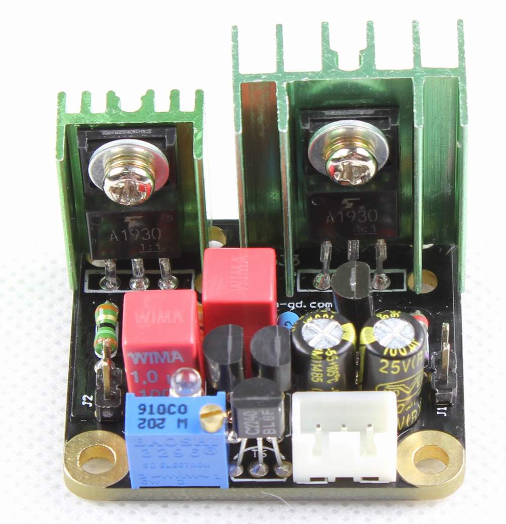
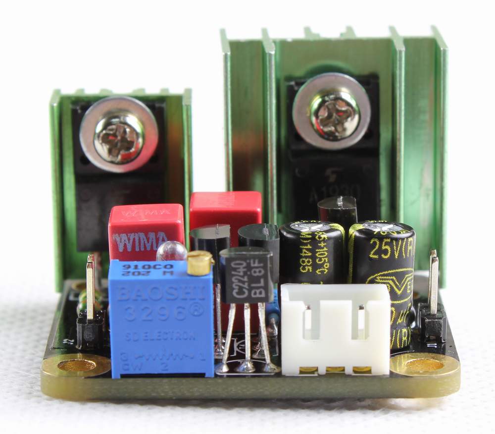
                                     
Detail views


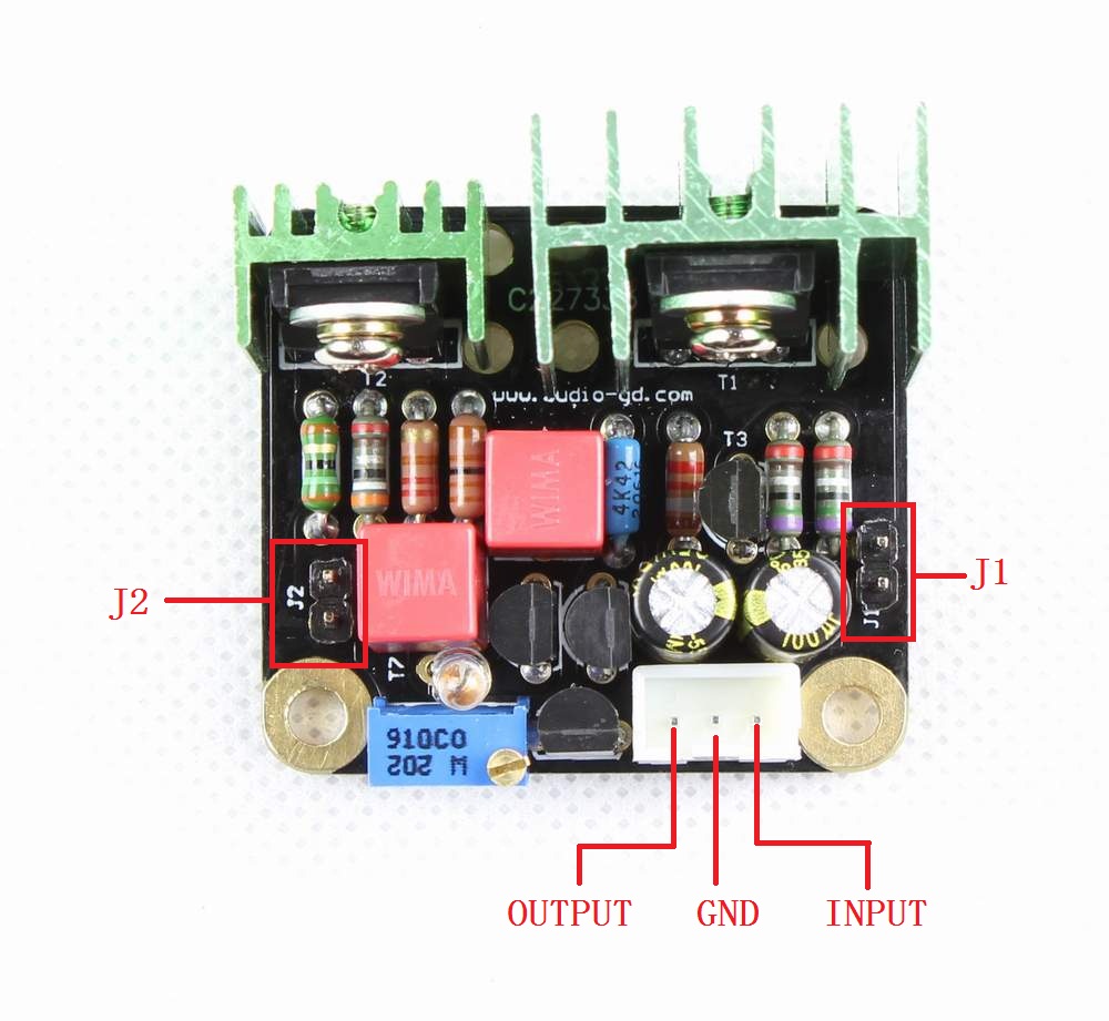
The advantage of the Class A PSU :
         The Class A design always is the best design in audio field . 
         The class A PSU  had some limit ,  the heat is a little hotter than the normal PSU  , the output current have limit , the Line Regulation and Load Regulation not as good as the normal PSU , because it is non-feedback design , but these all are not the points, it have the most neutral sound reproduce keep most DIYers like to applied it in their gears.

           The Class A PSU had very high input impedance and low output impedance can avoid power disturbs . It working at class A state , have the fastest output current response.   
Note:
     
1, The heat sinks have connected to GND, so take care while install in the gear.
         2, The adjustment resistor can adjust the output voltage, if you have not enough experiences, don't adjust it , we have adjust to standard output before shipment.
         3, Connect by wrong will shatter the PSU or the gear.
         4, While the PSU working will have some heat .
         5, There is better connect the input and GND , check the output voltage if correct as you expect then connect to the circuit .
        6, Even 70MA already suit the circuit require , but users still can setting to 140 MA see which one sound better for personal taste.
        7, Take care the input voltage if make it working over load.


Specs
 
Model Output voltage (VDC) Input voltage (VDC)  
PSU-A3V3 +3.3 +5 to +12V  
PSU-A5V +5 +7 to +15V  
PSU-A9V +9 +11 to +20V  
PSU-A12V +12 +14 to +22V  
PSU-A15V +15 +17 to +25V  
PSU-A18V +18 +20 to +28V  
PSU-A24V +24 +26 to +35V  


PSU-AN3V3 -3.3 -5 to -12V  
PSU-AN5V -5 -7 to -15V  
PSU-AN9V -9 -11 to -20V  
PSU-AN12V -12 -14 to -22V  
PSU-AN15V -15 -17 to -25V  
PSU-AN18V -18 -20 to -30V  
PSU-AN24V -24 -26 to -35V  
       
Custom order 3.3V to 50V (+/-) <250 MA and < 60V DC input.  


FAQ:
1 ,
I connected all wires  without wrong, but the output voltage very low. Why?
       Some reason as below:
       A, The load circuit current require more than the PSU output, try to setting at 150MA output.
       B, If setting at 150MA output still have low voltage, maybe the load circuit have large start current cause the PSU can't start.

2 , How to setting at 150MA otuput?
       Solder short or push into a jumper on the board.

3 , My circuit only require 20MA, does the PSU will shatter my circuit?
      Absolutely can't shatter the circuits .

4 , What function of the J2?
      The J2 for check the spare current of the PSU.   ( Spare current ) =  ( Out current )  -  ( Load current ) .
      For example, if the spare current is 25MA, the PSU setting at 80MA, it mean the load current is 80 - 25 = 55MA .
      If you have check the spare current , or don't want check the spare current anymore, you can left J2 hang or short it by solder or jumper .

5 , How to count the spare current ?
       Use a DC voltage meter, setting at 200MV or 2V , check the J2 voltage.  ( Spare current ) = ( Voltage MV) / 3.9 .
       For example, if check the J2 had 100MV voltage, the spare current = 100/3.9 = 25MA .


备案序号:粤ICP备05020367号

版权所有:          何庆华  睿志音响

Copyright(C) 2004   www.audio-gd.com    All Rights Reserved