|
Designing a matched Class A single ended pre-amp and
power amp
”@
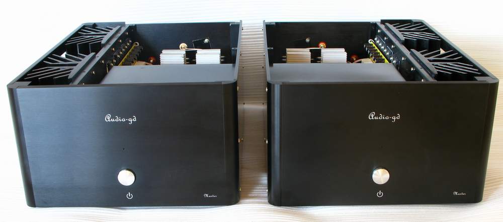
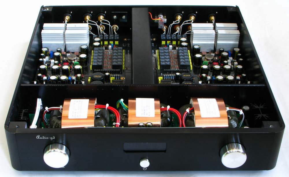
The ST-1
power amp and ST-7 pre-amp have been designed as a complimentary pair of
Class A single ended amps. The bulk of the discussion below is about the
power amp but a cursory glance will show that the gain boards on both
are similar. The pre-amp is dealt with briefly at the end of this
paper.
The
single ended Class A amplifier is a highly respected design with a
tradition going back to Linsley Hood. More recently it has been made
famous by Nelson Pass and other respected audio engineers. Class A, SE
amps have the characteristic of
operating over the whole
of the input cycle in such a way that the output signal is an exact
scaled-up replica of the input with no clipping. Draw on the mains power
supply is high and close to constant regardless of signal strength and
thus Class A amps are much less efficient than, for example, class AB
amps. Countering this, Class A SE amps produce even harmonics which
makes them highly regarded by audiophiles for their warmth, sound stage
and resolution.
While the original
Linsley Hood circuit was elegant and simple, it had a low power output.
The increases in power gained by later designs like those of PASS
brought with them certain problems. A differential input circuit has a
tendency to reduce the SE character of the design and though it can be
improved by re-tuning circuit components, the result is not as natural.
Another approach used in class A SE amps has been to use bridging
techniques but this is arguably an even less satisfactory solution than
the differential input method.
The
design of the ST-7 pre-amp and the ST-1 power amp is as much
philosophical as it is technical and brings to fruition many years of
experience. Combined in these amps is the driving power of an SS amp
along with the resolution, tonal colour and flavour of a SET valve amp.
On top of this comes easy maintenance and low cost.
Circuit design
analysis
The
design of an outstanding electronic circuit must be based not just on
technical specifications but should also take into account an
understanding of the acoustic fidelity of the individual components
used. Beyond this, a designer has also to anticipate how these
components will combine to produce a neutral and natural sound. It is
much more satisfactory to make good initial choices than to have to
apply add-on corrections later.
Inherent in this
classic SE amplification circuit is the problem that variations of the
operating current and output voltage can occur with temperature changes.
Control of these fluctuations is essential to prevent catastrophic and
expensive damage to speakers. Traditional solutions to this problem have
been:
1. the addition of
several thousand uF of high grade capacitance just prior to the output
terminal to block DC.
2. to employ a
differential circuit to limit DC drift [as exemplified by PASS
circuitry]
In pursuit of
perfection, a different approach has been taken with the design of the
ST-1 and ST-7 using dc servo to lock the operating points. The DC servo
circuit circuitry used here is based on a fresh examination of theory
and thus breaks away from more conventional thinking. The first stage of
the servo circuit uses an integrated amplifier to extract DC from the
signal while reducing AC. In addition a -6db buffer is present to reduce
any noise introduced by the integrated amplifier.
The
output of the DC servo again passes through the RC filter, then to the
feedback coupling capacitor to get rid of the alternating component,
yielding the pure dc component. When the DC level in the output is
changing, the DC servo output point TP1 changes accordingly. The V/I
variations pass the resistor and alter the operating point of the input
stage to restore OV output. The output dc is limited to 2MV during the
actual circuit test.
Looking
at the main amplifier, the circuit is quite straightforward, though it
deserves explanation. If the first stage of the circuit was to use a
constant current to obtain a high S/N ratio this would necessarily also
reduce the of Class-A single-ended character of the amplifier. Therefore
this stage does not use constant current source but instead allows other
parts of the circuit to enhance the S/N ratio.
The
second part is the critical main gain stage where most of the gain
occurs. The operational characteristic here significantly influences the
whole sound. If this stage only uses common-emitter circuit, the sound
is dense and warm, but blurred and lacking delicacy. With a desire to
reproduce the mid/high frequencies to convey the feeling of running
water, floating cloud and high transparency a different approach is
needed. So, a cascode
circuit which has the
desired timbre, becomes the logical choice here.
The next challenge is to keep the cherished timbre but at the same time
to reduce the wideband characteristics.
Cascode
transistors configured in common-base require biasing voltage to work
properly as the reference voltage circuit audibly effects sound quality.
Much time has been devoted to comparing the following reference voltage
methods.
1.
Zener diode
connected to the power supply loop
2.
Zener diode
connected to the signal loop
3.
LED connected
to the signal loop
4.
Resistor connected to the signal loop
5. Triode BE voltage
multiplier connected to the signal loop,
Of the five options:
1. has good body and
dynamics but lacks subtlety.
2. is improved on 1) but
still lacks delicacy
3. using a green LED the
sound was clear and fine in the upper frequencies but weaker than the
Zeners in low frequency. Interestingly, a blue LED gave different
results although all up LEDs had failings and also suffer from a short
life in this application.
4. using Dale resistors,
low frequency volume was down and in addition the depth of frequency
response was limited
5. using A970/C2240 the
mid-range is warm and clear while bass reproduction is brought slightly
forward with a good sense of reality.
While it might seem to
the casual observer that such distinctions are too fine to be
observable, it is the nature of Hi Fi audio that attention to such tiny
differences is essential to the design of outstanding equipment. The
above results were the result of numerous trials under controlled
conditions.
The
loading of this circuit is Constant current source that can enhance load
capacity, maximize output effectively and concurrently lower the
distortion. When the high current Darlington transistor”¦s [MJ11032/MJ11033]
operating current is
80MA, the sound quality is well balanced and delightful. Hence, this
circuit is set at 80MA approx.. The output current is enough to drive
the output transistors without using any pre-driver transistors.
To bring out an open and singing nature requires low open-loop gain.
This circuit”¦s open-loop gain is 39DB only. The -3DB frequency response
is at 55Khz. Closed loop gain is 27DB. The local feed back loop is
connected from the output of the voltage amplification parts but does
not re-join at the front-end round to give global feedback. Audiophiles
might appreciate this aversion to global feedback
The
design of this system also tested out a theory that a tubelike soft and
deep low frequency presentation would be favoured by the use of a low
damping factor. This was achieved by not using a pre-drive transistor.
Auditioning the completed system proved the theory to be correct though
interestingly, this form of design is counter to that conventionally
used in hi fi with huge dynamics.
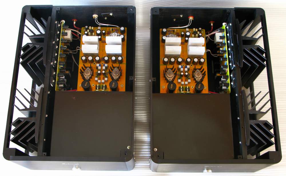
When
it is considered that many of the components in the output circuit are
in parallel the simplicity of the circuit becomes apparent. The output
of the power amp can be varied from 15W at 8 Ohm to 60W at 8 Ohm by
changing the number of output transistors. Board design will allow for
up to six pairs of transistors. The ST-1 uses
C5200”¦s in preference to A1943 as they offer superior linearity and the
uniformity. In the output stage constant current circuit, out of 6
transistors, one is for pre-driver, 5 are for output. The 45W/8 output
power needs approximately 2. 5 A electric current. To achieve this, the
1. 5 ohms resistance of the constant current flow circuit is obtained by
two 1/2W 3 ohm resistors in parallel.
The
amplifier uses local feedback in every stage. All components have been
selected to produce a tube like sound with superior accuracy.
Along
with the high operating current comes an increase in supply ripple and
potentially hum. An alternative to enhance SNR is to provide a voltage
regulator to the output stage. The stabilized voltage supply on the left
side of the power suppler diagram is for output and the supply on right
side is for voltage gain circuits. These voltage regulators
perform well and are of a well respected and recognized design. The
circuits have been re-designed to enhance temperature stability and to
suppress ripple capability.
The current consumption is
as high as 2.5A for 45W at 8ohm. For future upgrade of power output, the
current will be larger. For this reason the voltage regulator”¦s
transistors use a double parallel design which provides a safe working
margin with excellent linearity.
The power supply board can
house 200,000uf capacitor. When using 60,000uf the capacity is
sufficient for a 45W output. The ability of single bridge rectification
to enrich sound makes it well suited to this purpose.
Class-A
amplifier operates with a constant current draw and therefore require
less current regulation. While a 350W transformer would be sufficient
for a 45W output it is preferable that the transformer supplies perhaps
20 times more than the actual power consumption to reduce the problems
of mechanical vibration. It is intended that a 1000W transformer will be
used for each channel though it remains to be seen if audiophiles will
be prepared to pay the price for this extra capacity
With Class A-SE amplifier,
audiophiles are more concerned about SNR and any noisy, remnant sound
which would mask the small signal delivery as such noise would affect
the mood and destroy the quality of the image. The amplifier”¦s output
noise is only 0.1MV, the un-weighted SNR is 104DB, which is exceedingly
high for any commercial product. The noise cannot be heard even the ear
touching the 90DB sensitivity loud speaker.
”@
|