|
NFB-28 upgrade DSD support
Upgrade kit price :
For the unit shipping before Feb 2014 : USD70 (Exclude shipping
cost.)
Include USB-32DSD with wires
MCU
One stock 100MHz clock
16 pcs DALE resistors
1 pc resistor with wire
(if you want the TCXO 100MHz clock, total
price is +USD20, check the built in clock if 80MHz before place the
order ,if it is 100MHz already, don't need order the clock replacement.)
For the unit shipping after Feb 2014 :USD10 (Exclude shipping cost.
)
Include MCU
Newest Firmware chip
4 pcs DALE resistors
1 pc resistor with wire
2 pc wires
Please note:
1,After upgrade , the functions had same as the current NFB-28.
2, Before the upgrade, please uninstall the old driver, after
finished the upgrade, install the newest driver .
http://www.audio-gd.com/Pro/dac/USB32/USB32EN.htm
For the products
shipping since 14th.Aug.
2014 Download
the USB32 driver version 1
3, The upgrade had the soldering necessary and a bit complex so it may had the risk
to damage the unit if
with wrong operate .
4, Before take off the top cover, must pull off the power cable .
After finished the upgrade, there is better test it if working well
as expect with a cheapest headphone.
5, We have improve the unit continuously , if your unit had
different parts and you had confuse, please contact us feel free
,send the photo and ask the questions.
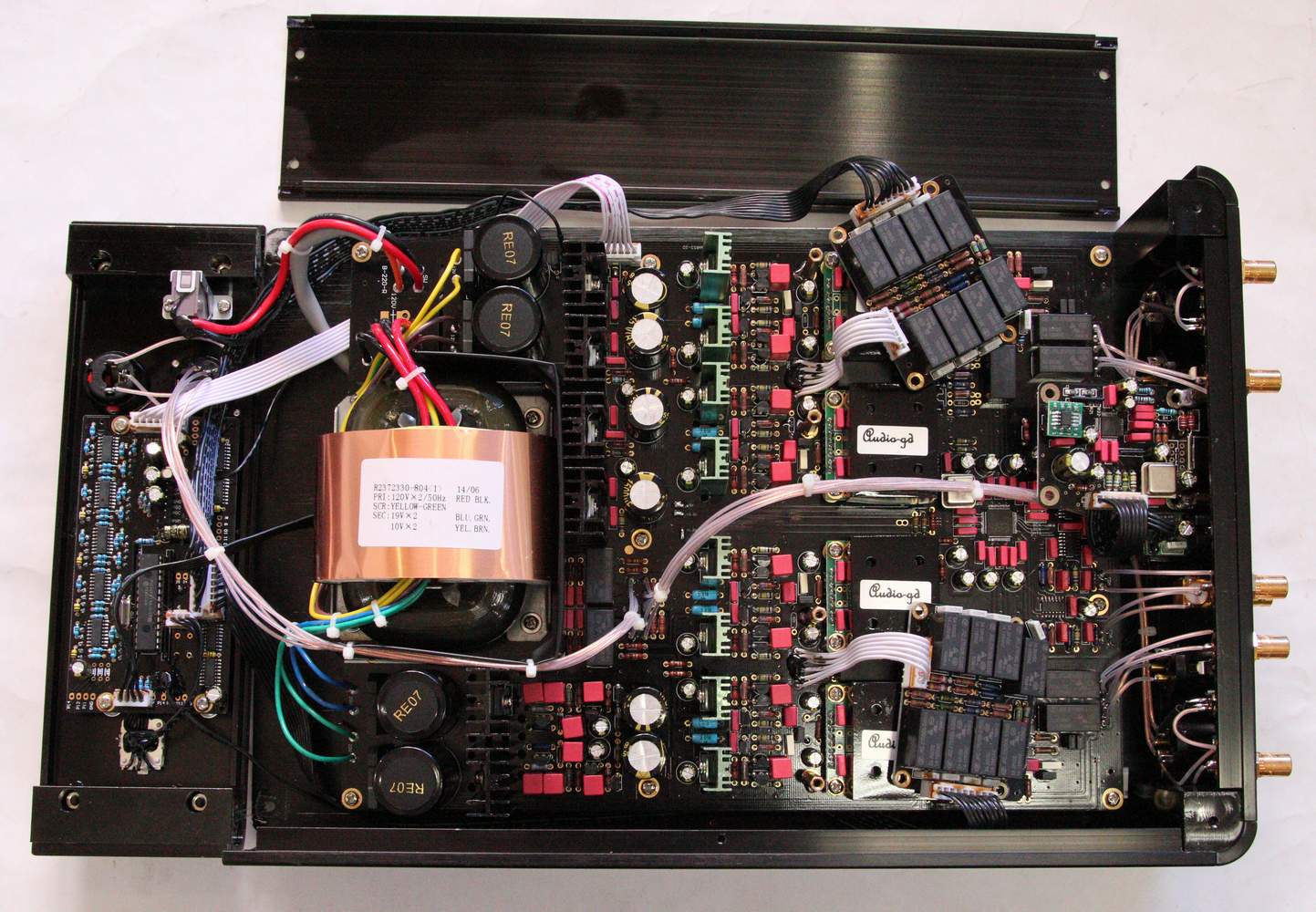
Upgrade steps :
Step 1, Pull off the power cable, take off the top cover, front
plate and the left side board , take off the two volume boards. Be
care don't broke the wires in the unit. All
modify don't need take off the main board.

Step 2, The unit was shipping before Feb. 2014 want to replace the
USB module and replace the 80MHz clock by 100MHz (for support up to
384KHz ) .
The unit was shipping after Feb. 2014 don't want replace the USB module
and the clock,
just replace the newest firmware chip on the USB module correctly .
While you place the order of the upgrade kit please check if want to
replace the 80MHz clock to 100MHz, please inform the
series number of the unit , let us check if want to replace the USB
module.
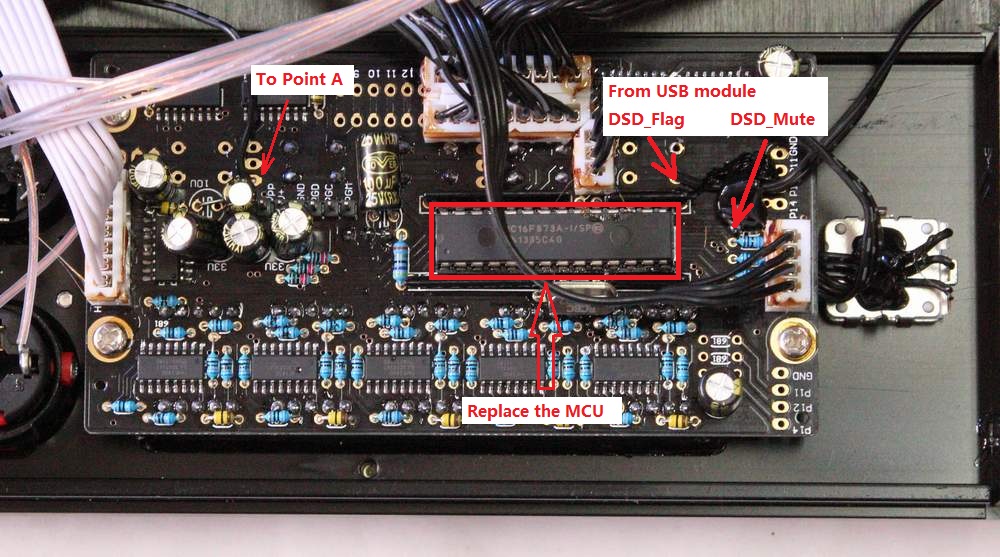
Step 3, Replace the MCU on the display board ( please note the MCU
had direction, and make sure all pins had push into the IC socket
correctly ). Solder the 3
wires on the display board.

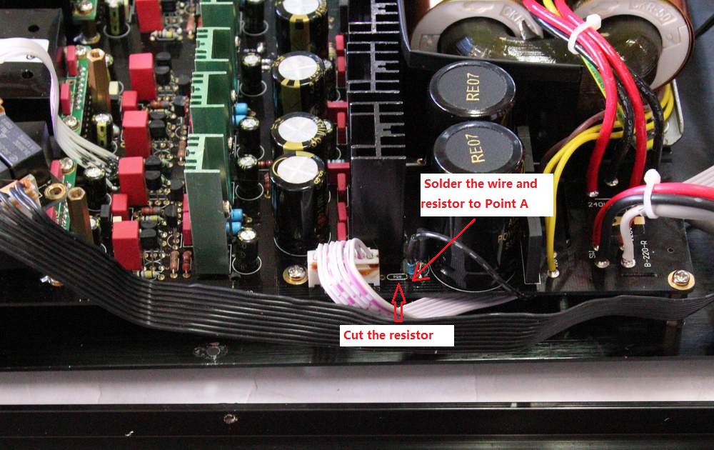
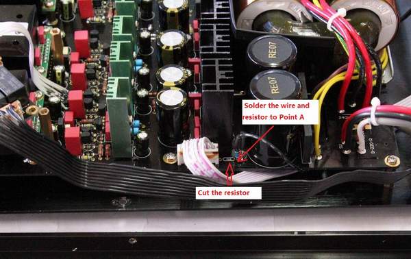
Step 4, Cut one resistor and solder the resistor
with wire on the one pad of the original resistor, as below photo.
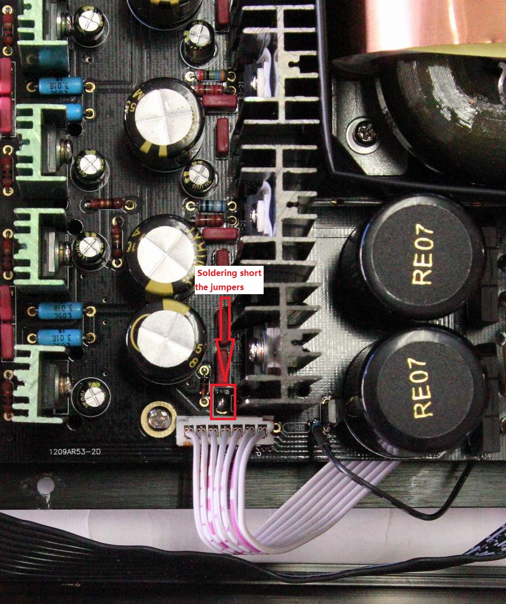
Step 4, Solder short the two jumper pins as below photo (don't need
solder off the two jumper pins).

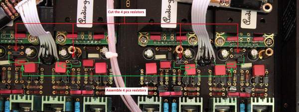
Step 5, Cut the 4 pcs resistors as below photo. And solder on the
new 4 pcs resistors as the below photo.
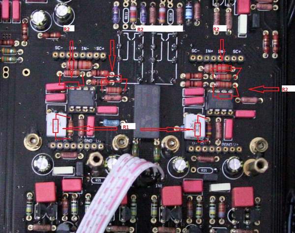
Step 6, if your unit was shipping before Feb. 2014, you want to take
off the 4 pcs ACSS module and solder 12 pcs resistors in total on the original
resistors as below photo, the original resistors don't want take
off, be care don't broke the pins of the ACSS module while pull off
and push on. The unit was
shipping after Feb . 2014, ignore this step .
|